Page 3
Sorry
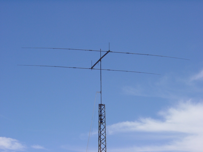
I don't have pictures of cranking up the mast, but the crummy
winch made it a dicey process and I'll settle for just getting it up
there. Here the OB2-40 is at it's final height and the mast is
mounted in the rotator. Notice how little sag there is in the
elements, which are about 49 feet long tip to tip. This is a
really strong antenna.
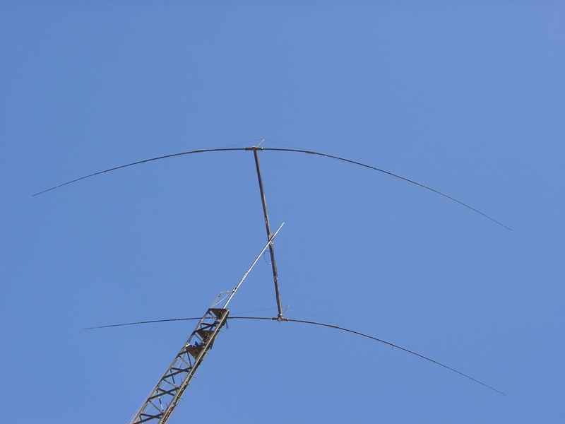
I had no idea, though, that this antenna would get tested so severely so soon after I put it up. We get strong wind gusts here in Arizona during the springtime, but this year it has been especially a problem. I have a reasonably accurate wind gauge on a pole above my house (about thirty feet above the ground in total), and several times over the next few days I measured peak gusts over 90 miles per hour. Gusts over 70 miles per hours were too numerous to keep track of. The OB2-40 survived in fine shape, but it was simply awful to have to watch the beating it took. The deflection of the elements in the picture below is all horizontal ... that isn't element sag.
OK, then ... on to the tribander. The boom comes in four sections, and gets spliced together in the same fashion as I described for the OB2-40. I rigged a couple of boards to support the 30' long boom and started assembling the elements. Here you can see the sixteen element-to-boom clamps mounted in position, all of which by the way are clearly marked on the boom by OptiBeam. The insulators come preattached to the saddles, and it would be pretty difficult to mess up the rest of the assembly.
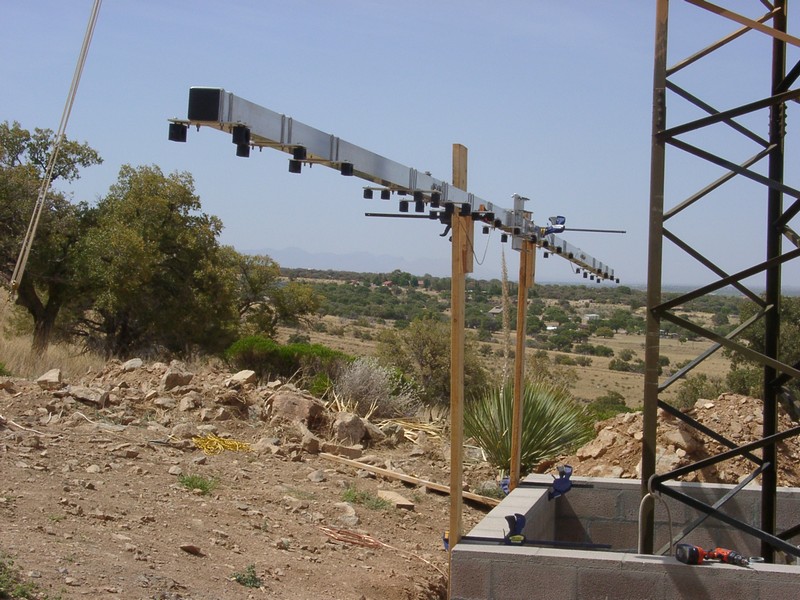
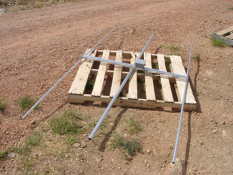
The phasing line between the driven elements requires rather precise spacing, so I followed the manual's suggestion and pre-assembled those portions (with the balun) before attaching them to the boom as one piece. These are the driven element center sections, which are shipped with the center insulator already in place.
AB7E Home
Tower and Antenna Project Home
Previous Page Next Page

I had no idea, though, that this antenna would get tested so severely so soon after I put it up. We get strong wind gusts here in Arizona during the springtime, but this year it has been especially a problem. I have a reasonably accurate wind gauge on a pole above my house (about thirty feet above the ground in total), and several times over the next few days I measured peak gusts over 90 miles per hour. Gusts over 70 miles per hours were too numerous to keep track of. The OB2-40 survived in fine shape, but it was simply awful to have to watch the beating it took. The deflection of the elements in the picture below is all horizontal ... that isn't element sag.
OK, then ... on to the tribander. The boom comes in four sections, and gets spliced together in the same fashion as I described for the OB2-40. I rigged a couple of boards to support the 30' long boom and started assembling the elements. Here you can see the sixteen element-to-boom clamps mounted in position, all of which by the way are clearly marked on the boom by OptiBeam. The insulators come preattached to the saddles, and it would be pretty difficult to mess up the rest of the assembly.
The phasing line between the driven elements requires rather precise spacing, so I followed the manual's suggestion and pre-assembled those portions (with the balun) before attaching them to the boom as one piece. These are the driven element center sections, which are shipped with the center insulator already in place.
AB7E Home
Tower and Antenna Project Home
Previous Page Next Page